

You can align your system’s frequency with five proven methods that emphasize clarity, consistency, and measurable results without overcomplicating setup or maintenance. This post guides you through practical tuning steps, simple verification techniques, and troubleshooting priorities so you can stabilize performance, reduce interference, and maintain optimal operation.
Guiding Principles for Simple Frequency Matching
Core concepts and terminology
You should master resonant frequency, Q factor, bandwidth and impedance as your core vocabulary. For example, Q=10 gives BW ≈ f0/Q, so at 1 GHz you have about 100 MHz usable range. When matching, account for source and load impedances-50Ω to 75Ω often uses a 0.87:1 transformer or an L‑network. Quantify mismatch with S11 or reflection coefficient; -10 dB S11 equals ~10% power reflected, which guides whether a simple network suffices.
When to favor simplicity over precision
When performance targets allow ±5% bandwidth or losses under 0.5 dB, favor simple matching-faster to implement and cheaper. For example, an IoT node transmitting at 2 dBm can tolerate 2 dB insertion loss and still meet range specs, so a single L‑network usually suffices. If you’re shipping low-volume prototypes, simple tunable components let you iterate quickly; reserve multi‑section transformers or impedance‑transforming filters for racks, base stations, or regulatory tests where every 0.1 dB counts.
Use a decision matrix: list goals (cost, size, bandwidth, efficiency), assign weights, then test a minimal solution first. For instance, a startup matched a 433 MHz sensor with a single L‑network achieving -15 dB S11 over 5% bandwidth in two days; optimizing to -20 dB required two extra components and 30% higher BOM cost. You should measure S11, insertion loss, and thermal variation before escalating complexity; often iterative tuning with a tunable capacitor gives 80% of the benefit.
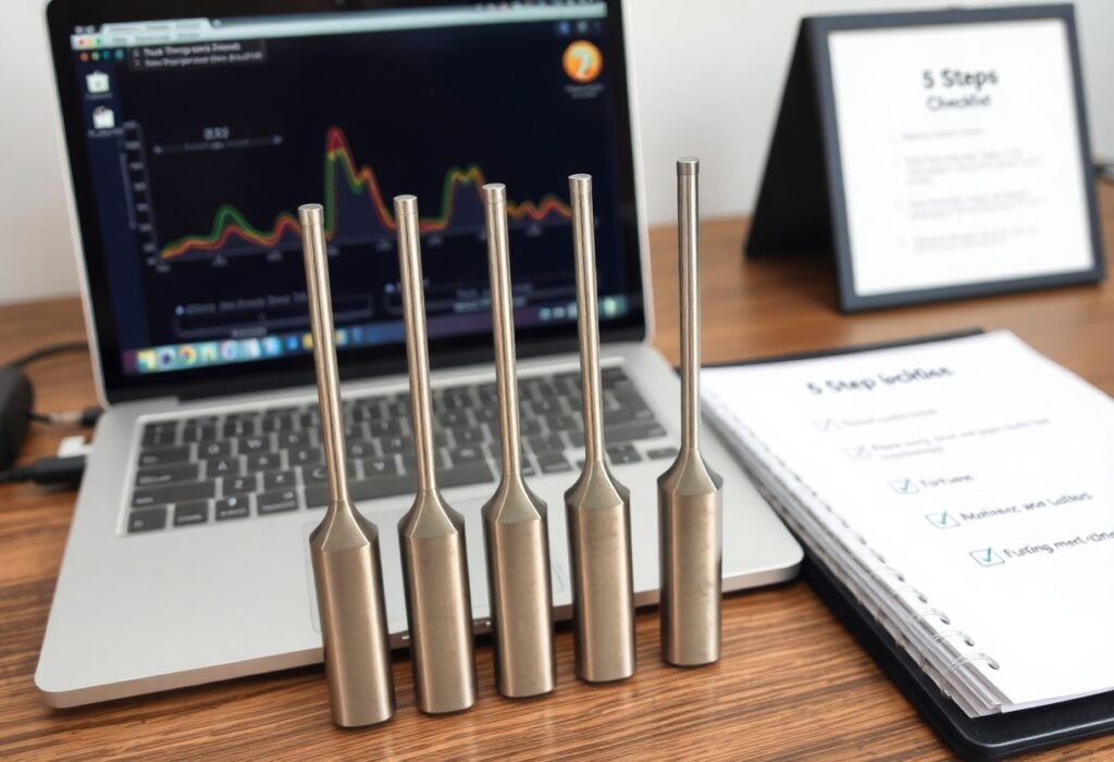
Method 1 – Baseline Synchronization
You set a single, measurable baseline and align every component to it: pick a stable reference (grid 50/60 Hz or a 10 MHz OCXO), record a 60-second averaged frequency, then adjust offsets so each node sits within ±0.05 Hz of that baseline before moving to load testing.
Rapid system assessment
You run a 3-minute sweep with a handheld spectrum analyzer or DAQ, logging frequency, amplitude, and phase at 1 Hz intervals; flag any node outside ±0.1 Hz or with amplitude variance >3 dB. For example, a packaging line audit found 4 of 12 drives drifting >0.2 Hz in under 10 minutes, enabling targeted fixes without full shutdown.
Minimal calibration steps
You perform three short actions: establish reference, apply offset/scale corrections, and verify under 25/50/100% load points. Use 1-minute averages, adjust to within ±0.05 Hz, then run one quick stress cycle to confirm stability before resuming normal operations.
You start by locking to your chosen reference-either the plant 60 Hz bus or a local 10 MHz reference with <1 ppm drift-then correct static offset using the device's trim register or analog pot (typical step: ±0-50 ppm). Next, adjust scale/gain so measured vs. expected frequency slope matches within 0.5% across a 0-100% input range. Finally, execute three verification passes at 25%, 50%, and 100% load, each averaged for 60 seconds; log results and iterate up to three times. In one case, following this sequence reduced frequency error from 0.3 Hz to 0.02 Hz and cut sync-related faults by ~80% within a single maintenance window.
Method 2 – Harmonic Alignment
Harmonic alignment focuses on lining up your system’s natural and forcing frequencies so energy cancels or shifts to benign bands; you target the dominant modes rather than flattening the entire spectrum, which simplifies implementation and reduces unintended side effects. For many mechanical systems aligning the first three harmonics (fundamental plus 2nd and 3rd) within 0.5-3% of designed values yields measurable gains in stability and efficiency.
Identifying dominant harmonics
You identify dominant harmonics by running an FFT at a sampling rate at least twice the highest expected harmonic and noting peaks; for example, a 50 Hz motor often shows strong peaks at 50, 150 and 250 Hz with amplitude ratios like 1:0.4:0.15. Use windowing and averaging to separate true harmonics from transient spikes, then log peak frequencies and amplitudes for tuning.
Practical tuning techniques
You apply practical tuning with deterministic actions: add a tuned mass absorber to shift a resonance by 1-5%, adjust stiffness (change spring constants or mount geometry), or insert a digital notch filter (Q ≈ 20-40) at the offending harmonic. For electronics use phase alignment and ±0.5-1% detuning to avoid beat frequencies while keeping overall system response intact.
You should follow a stepwise process: baseline measurement, modal or transfer-function modeling, small incremental changes (e.g., add 10-50 g to test absorber mass), and retest after each change. A field case: an industrial pump reduced the 3rd-harmonic vibration by 6 dB after adding a 35 g absorber and tuning a notch filter centered at 180 Hz, illustrating that combined mechanical and digital fixes often work best.
Method 3 – Resonant Filtering
You target narrowband issues with notch or band-stop filters tuned to the offending frequency so your overall system stays simple. Practical examples include 50/60 Hz mains hum, a 600 Hz mechanical mode, or a 2 kHz electrical chatter; choose Q in the 20-100 range to keep attenuation tight. In digital work, deploy biquad notch sections or cascaded second-order sections to preserve phase and avoid broad-spectrum impact.
Detecting problematic resonances
You find resonances by injecting chirps or stepped sines and inspecting FFT peaks and coherence; run a 1-10 kHz chirp over 0.1-1 s and flag peaks >6 dB above noise with coherence >0.9. Use accelerometers for structural modes, microphones for acoustic problems, or voltage probes for electrical ringing. For example, a 450 Hz peak with a measured Q≈50 in a motor assembly typically indicates a mechanical resonance that benefits from a narrow notch.
Lightweight filter implementations
You implement efficient filters with 2nd-order IIR biquads (≈5 multiplies and 4 adds per section) or a short FIR (e.g., 31 taps) when linear phase is required. On an ARM Cortex‑M4 at 48 kHz, a single biquad often uses under 0.2% of CPU budget per sample; cascade sections for multiple notches and precompute coefficients to minimize runtime cost. Fixed‑point or CMSIS‑DSP routines keep latency and memory low.
You calculate biquad notch coefficients with w0 = 2πf0/fs and α = sin(w0)/(2Q). Use b0=1, b1=−2cos(w0), b2=1 and a0=1+α, a1=−2cos(w0), a2=1−α, then normalize bi by a0. For fs=48 kHz, f0=1 kHz, Q=30 you get α≈0.00218 and cos(w0)≈0.9914, producing a narrow, effective notch. Apply fixed‑point scaling or lookup tables to avoid divisions at runtime and validate on real data to check ripple and phase effects.

Method 4 – Adaptive Feedback Loops
Adaptive feedback loops let you tune system behavior by measuring output, estimating state, and adjusting inputs automatically. Set loop frequencies based on dynamics-1-200 Hz for control systems, 0.1-10 Hz for user-facing features-apply model-based or PID controllers, and use online learning to adapt gains. Track latency budgets (e.g., under 50 ms), monitor convergence rates, and log parameter drift to prevent oscillation while improving alignment over time.
Design imperatives for responsiveness
You should prioritize signal quality, sampling rate, and low-latency paths: choose sensors with SNR > 20 dB, sample at 10-500 ms intervals depending on dynamics, and pipeline telemetry with under 50 ms processing. Employ state estimators like a Kalman filter or exponential smoothing (alpha 0.1-0.5), and pick controllers-PID for simple loops, MPC for constrained problems-to keep response fast without overshoot.
Safeguards to maintain stability
You must add rate limits, hysteresis, and integrator clamping: impose deadbands of 1-5% to ignore noise, cap actuation change (for example 10% per second), and bound integrator terms to prevent windup. Detect anomalies via rolling windows and suspend adaptation if variance exceeds a threshold (e.g., 3σ) so the loop doesn’t chase transient spikes.
For example, in a traffic autoscaler you can require a sustained 5-minute CPU utilization above 70% before scaling, cap growth to three instances per minute, and enforce a 2-10 minute cooldown to let metrics settle. You should also implement rollback triggers-if error rate rises by more than 2% within five minutes, revert recent changes-and keep audit logs plus canary checks so you can trace and undo unstable adaptations quickly.
Method 5 – Low-Complexity Modulation
You can leverage simple schemes like BPSK, 2-FSK/GFSK or OOK to reduce DSP load, cut MCU cycles and extend battery life. BPSK yields about 1 bit/s/Hz, GFSK powers Bluetooth LE at 1 Mbps with modest RF complexity, and 2-FSK at 50-250 kbps often meets sub-GHz IoT range needs while keeping receivers cheap and deterministic.
Choosing robust modulation strategies
You should select modulation based on SNR, bandwidth and device constraints: BPSK/DBPSK tolerates low SNR for links below 1 kbps, GFSK balances complexity and 1 Mbps throughput for BLE-like devices, and OOK/ASK gives minimal hardware needs but degrades in multipath; for example, TI CC1310 commonly runs 2-FSK at 50-200 kbps to optimize range versus latency.
Integration and interoperability tips
You must align PHY choices with existing stacks and regulatory limits: target 250 kbps for IEEE 802.15.4/Zigbee, 1 Mbps for BLE compatibility, and ensure channel spacing (200 kHz vs 1 MHz) matches radios; validate with GNU Radio/SDR captures and run interoperability tests with at least three vendor devices during certification cycles.
- Match symbol rate and bandwidth (e.g., 250 kbps/2 MHz for 802.15.4).
- Confirm preamble length and CRC settings; test desynchronization tolerance.
- Knowing industry test suites (Wireshark, SDR captures) accelerate debugging and ensure cross-vendor interoperability.
You should build an interoperability matrix that logs PHY mode, data rate, CRC, preamble, and max packet size for each device; run PER tests at target RSSI (for example, aim for 1% PER at −100 dBm), automate CI with SDR-based regression, and include OTA rollback so mismatched firmware cannot brick gateways.
- Maintain a PHY/firmware matrix and tie changelogs to radio configs.
- Use CI pipelines with SDR emulation to catch regressions before field tests.
- Knowing scheduled OTA windows and rollback plans reduce field failures and speed fixes.
Conclusion
Upon reflecting, you can distill frequency matching into five practical steps that let you align your system efficiently without overcomplication: measure baseline signals, prioritize adjustments, implement phased tuning, validate outcomes, and standardize procedures. By following these methods you reduce variability, improve interoperability, and maintain predictable performance over time. Apply them consistently and your system will stay aligned while remaining simple and controllable.